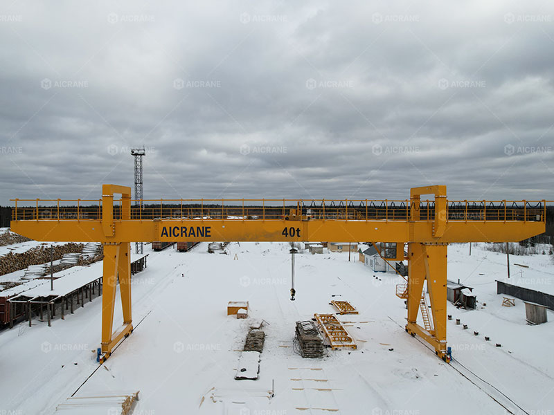
A 40 ton gantry crane is a medium-to-heavy-duty lifting solution widely used in industries such as steel fabrication, precast concrete production, shipyards, railway freight yards, power plants, and large equipment assembly workshops. Its ability to lift and transport heavy loads efficiently across outdoor or semi-outdoor working areas depends entirely on the coordinated performance of its main working mechanisms.
Understanding the main working mechanisms of a 40 ton gantry crane is essential for equipment selection, operation, maintenance planning, and cost optimization. This article provides a detailed explanation of how each core mechanism works, how they interact, and why proper design is critical for safe and reliable crane operation.
1. Overview of Gantry Crane Working Mechanisms
A 40 ton gantry crane typically consists of the following main working mechanisms:
-
Hoisting mechanism
-
Trolley traveling mechanism
-
Crane traveling (long travel) mechanism
-
Electrical and control mechanism
-
Safety and auxiliary mechanisms
Each mechanism performs a specific function, but all must operate in harmony to ensure smooth load lifting, precise positioning, and stable crane movement.
2. Hoisting Mechanism: The Core Lifting System
The hoisting mechanism is the most critical working mechanism of a 40 ton gantry crane, as it directly handles the load.
2.1 Main Components of the Hoisting Mechanism
-
Electric hoisting motor
-
Gear reducer
-
Brake system
-
Wire rope or chain
-
Hoist drum
-
Hook block (often with pulley groups)
For a 40 ton capacity, the hoisting mechanism usually adopts a wire rope hoist with multiple reeving systems (commonly 4/2, 6/2, or 8/2 rope configurations) to distribute the load evenly and reduce stress on individual components.
2.2 How the Hoisting Mechanism Works
When the motor rotates, torque is transmitted through the reducer to the drum. The wire rope winds or unwinds around the drum, raising or lowering the hook and load. The braking system ensures:
-
Safe stopping during operation
-
Load holding when power is off
-
Emergency braking in abnormal conditions
2.3 Hoisting Speed and Control
A 40 ton gantry crane typically uses dual-speed or variable frequency drive (VFD) control for hoisting. This allows:
-
Slow lifting for precise positioning
-
Smooth acceleration and deceleration
-
Reduced load swing and mechanical shock
3. Trolley Traveling Mechanism: Horizontal Load Movement
The trolley traveling mechanism moves the hoist assembly horizontally along the main girder(s) of the gantry crane.
3.1 Structural Role of the Trolley
The trolley carries:
-
Hoisting mechanism
-
Load during lifting and movement
It runs on rails installed on top of the gantry girder(s), making it essential for accurate load positioning.
3.2 Components of the Trolley Mechanism
-
Trolley frame
-
Traveling motor
-
Reducer
-
Wheels and bearings
-
Rail system
3.3 Working Principle
Once the load is lifted to a safe height, the trolley motor drives the wheels along the girder rails. The movement allows the load to be positioned anywhere within the crane span.
For a 40 ton gantry crane, trolley systems are designed with:
-
High rigidity frames
-
Anti-slip wheel materials
-
Precise alignment to prevent rail wear
3.4 Anti-Sway Considerations
During trolley movement, improper acceleration can cause load swing. Modern 40 ton gantry cranes often integrate:
-
VFD-controlled trolley motors
-
Anti-sway logic via PLC systems
These features significantly improve safety and positioning accuracy.
4. Crane Traveling Mechanism: Long-Distance Movement
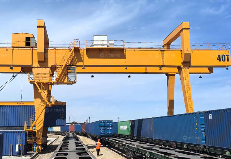
The crane traveling mechanism (also called the long travel mechanism) enables the entire rail gantry crane to move along ground rails or paved surfaces.
4.1 Rail-Mounted vs Wheel-Mounted Designs
A 40 ton gantry crane may be:
-
Rail-mounted (common in precast yards, steel plants)
-
Wheel-mounted or rubber-tyred (for mobile applications)
Rail-mounted systems offer higher stability and load capacity, while wheel-mounted designs provide flexibility.
4.2 Key Components
-
Traveling motors (usually two or more)
-
Gear reducers
-
Traveling wheels
-
End carriages
-
Rail system or ground wheels
4.3 Synchronization Mechanism
To prevent skewing or uneven movement, 40 ton gantry cranes often use:
-
Synchronous motor drives
-
Electrical anti-skew systems
-
Mechanical shaft coupling (in some designs)
This ensures smooth, straight-line travel and reduces rail wear.
5. Electrical and Control Mechanism: The “Brain” of the Crane
The electrical and control mechanism coordinates all crane movements and ensures operational safety.
5.1 Power Supply System
Common power supply methods include:
-
Cable reel systems
-
Festoon systems
-
Conductor bars
The choice depends on travel length, site conditions, and maintenance preferences.
5.2 Control Modes
A 40 ton double girder gantry crane typically supports:
-
Pendant control
-
Remote control
-
Operator cabin control
Remote control is increasingly popular for improving operator safety and visibility.
5.3 PLC and VFD Integration
Modern 40 ton gantry cranes rely on:
-
PLC systems for logic control
-
VFDs for speed regulation
This combination allows:
-
Precise motion control
-
Reduced mechanical stress
-
Energy-efficient operation
6. Safety and Auxiliary Mechanisms
Safety mechanisms are essential for heavy lifting operations, especially at 40 ton capacity.
6.1 Load Protection Mechanisms
-
Overload limiters
-
Load monitoring sensors
These prevent lifting beyond rated capacity.
6.2 Motion and Travel Safety
-
Hoisting height limit switches
-
Traveling end limit switches
-
Emergency stop systems
6.3 Outdoor Operation Protection
Since 40 ton gantry cranes often work outdoors, auxiliary mechanisms may include:
-
Wind speed alarms
-
Rail clamps
-
Anchoring devices
-
Buffers and shock absorbers
These features protect the crane during strong winds or unexpected stops.
7. Coordination of All Working Mechanisms
The true efficiency of a 40 ton gantry crane lies not in individual mechanisms, but in their coordination. During a typical operation:
-
The hoisting mechanism lifts the load
-
The trolley traveling mechanism positions it horizontally
-
The crane traveling mechanism moves the load to the target area
-
Electrical and control systems ensure smooth transitions
-
Safety mechanisms continuously monitor operating conditions
This integrated operation enables high productivity, precision handling, and long service life.
8. Conclusion
The main working mechanisms of a 40 ton gantry crane – including hoisting, trolley traveling, crane traveling, electrical control, and safety systems—form a highly integrated lifting solution. Each mechanism plays a vital role in ensuring safe, efficient, and precise material handling in demanding industrial environments.
A well-designed 40 ton gantry crane combines robust mechanical structures with advanced control technology, offering not only lifting power but also operational reliability and long-term value. Understanding these mechanisms helps users make informed decisions in crane selection, operation, and maintenance, ultimately maximizing return on investment.